I remember my first programming course in college on Visual Basic (I’m not as old as that statement makes me sound). I didn’t know the first thing about computer programming. I remember thinking to myself, “I’m finally going to learn how computers actually work.” I couldn’t have been more wrong.
Ever since then, I’ve had a growing obsession with learning how computers work. Eventually, I came across the Nand-2-Tetris project (they also have a Coursera version of their project). The idea is to build a virtual computer starting from a primitive logic gate called a Nand (Not-And) gate.
Part 1 of the course involves building the virtual 16-bit computer itself (called the “Hack” computer) as well as an assembler for that computer’s machine language.
Note: This is my personal reflection of the course. The intended audience for this post is someone either taking the course and feeling stuck, or someone with programming experience interested in giving Nand2Tetris a shot. I’d consider knowledge of basic logic gates a prereq for this post.
High Level Programming vs Boolean Logic
The first hurdle to writing logic gates is the paradigm shift to combinational logic from a more sequential, imperative, modern, C-style language such as Java, Python, Javascript, Go, etc.
For example, Multiplexers and Demultiplexers (Mux and Demux for short) really threw me for a loop. I studied the desired functionality and recognized the problem that needed to be solved, but I only had sequential, imperative knowledge and experience to solve it with. I wanted so badly to put if... then... else control flow in my logic gate. But in the world of combinational boolean logic, there is no program counter. There is no notion of sequential instructions or sequential control flow. Everything just “is.” Inputs are received and outputs are calculated, with only the laws of physics to govern how fast the output is “computed.”
Demux:
Let’s look at the interface and logic of the demultiplexer, for example.
# HDL (Hardware Definition Language)
CHIP Demux
IN in, sel
OUT a, b

if sel == 0 then a=in and b=0
if sel == 1 then a=0 and b=in
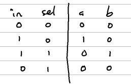
Above is an abbreviated version of the chip interface that is given to you to build. I like to think of this chip as a router chip (or data distributor chip). You give it an in value and a selection bit (sel) to control where that in value gets routed to.
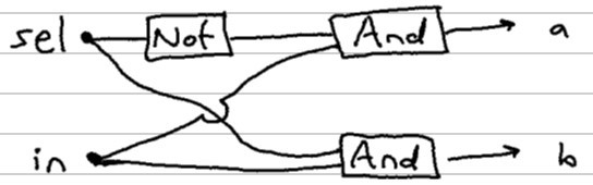
If the sel bit is 0, then the b output pin must also be zero. Then that same sel bit is negated by a not gate and passed into the and gate used to determine the a output. I encourage you to pass in the inputs in the truth table below to verify how the gate works.
It might be interesting to see what this same logic would look like in a simple, not-so-idiomatic Python function.
def Demux(in, sel):

    if sel == 1:
        a = 0
        b = in
    else:
        a = in
        b = 0

    return (a, b)

# we could call that like this (using Tuple unpacking)
a, b = Demux(1, 0)

# a == 1; b == 0
Because if statements aren’t really a thing in combinational logic like HDL, let’s refactor our function to only use boolean logic.
def Demux(in, sel):

    a = in and not sel
    b = in and sel

    return (a, b)

# once again:
a, b = Demux(1, 0)

# a == 1; b == 0
This was my first eye-opening experience in the course. It wasn’t a total shock that boolean logic could be used to replace a simple if/else statement, but going through the exercise of implementing it myself was at least a little mind bending.
The Role of Demux and Mux
I remember learning about logic gates a long time ago following a late-night rabbit hole about how computers work. It was still hard to fathom how primitive logic gates could possibly be arranged to do the complex tasks computers are capable of. I think Mux and Demux were huge missing pieces for me bridging the gap between primitive logic gates and modern computing.
One specific example I couldn’t comprehend was how logic gates could be used to create GBs of RAM in a computer. Even a simple 1-bit register wouldn’t be possible without a Mux gate. String 16 of those 1-bit registers together and we have a 16-bit register - the smallest addressable unit of our “Hack” computer’s RAM. And from there, we bootstrapped ourselves a nested hierarchy of exponentially growing RAM chips:
- 8-register (
RAM8) chips from 8registers - 64-register (
RAM64) chips from 8RAM8chips - 512-register (
RAM512) chips from 8RAM64chips - and so on… all made possible by certain types of
DemuxandMuxhelping to determine whether we’re updating a value at an address, or retrieving (or “probing”) its value
Pins vs Arguments
Writing HDL felt pretty similar to writing high level programming language code. I’m using a text editor and checking my work digitally. I failed to keep in mind that what I was creating was intended to simulate a physical device. Inputs and outputs of a chip are pins and buses, not arguments and parameters. Let’s consider another hypothetical Python function below:
def myfunc(a, b):
    # do stuff here
That looks like a standard python function signature. No big deal. But wouldn’t it look weird if you saw something like this?:
def myfunc(a[0], b[4]):
    # do stuff here
What does that even mean? The arguments a and b are meant to act as placeholders, not actual values. At this point, they don’t even have types associated due to Python’s flexible typing system. So why are we indexing into these arguments? It’s nonsensical.
But that’s perfectly acceptable when working with data buses and pins in chips:
Mux4Way16(... sel[0] = somevalue, sel[1] = othervalue);
The above chip takes a two-bit bus named sel as input. Because these are essentially just hardware pins, we can “assign” two different values to each of the sel bits (pins). The lesson here: although these chip definitions look and feel like functions in a software program, they represent physical pins passing voltages around as values.
The ALU
Creating the ALU was probably the most fascinating part of the course. It really deserves its own dedicated post, but I’ll summarize a few points here. This part gets even more dense than the previous sections… but hopefully it makes sense!
Let’s first consider an interesting method of incrementing a binary digit. We’ll start with the binary representation of 6 which is 0110.
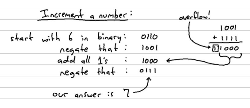
Note: This “all 1’s” value represents -1 in Two’s Complement. So “add all 1’s” really means add -1.
Even after working it out by hand several times, it’s hard for me to wrap my mind around how this works. If you take your input digit, negate its bits, add “all 1’s” to it (equivalent to subtracting by 1), then negate that output, you’re left with your original number incremented by 1.
Part of the magic here is due to taking advantage of an interesting property of Two’s Complement binary representation. When you execute a binary negation on a number, it’s similar to multiplying by -1 and then subtracting 1 from that. For example:
- 6 (
0110) negated becomes -7 (1001) - -8 (
1000) negated becomes 7 (0111)
Those two examples above are key to understanding this transformation:
- We start with 6
- negate that, which yields -7
- Subtract 1 from that, giving us -8
- Then negate that result giving us 7, our final result.
Incrementing a number by 1 is one of the compute operations supported by the “Hack” computer’s ALU that has been designed for us. There are many computations the ALU is capable of executing with one standardized chip interface: a 16-bit x value, a 16-bit y value, and a handful of control bits that act like a data pipeline for how we should transform our x and y input values.
The amazing thing about the ALU is designing it to handle many different types of computations, but from the same standard chip interface. Any one of these computations on their own would be trivial to implement.
Below is the ALU representation of our same increment operation (using our same 4-bit numbers from before for simplicity):
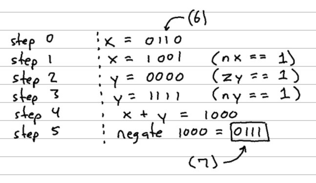
Let’s unpack some of those steps there:
- step 0:
xis the number we want to increment, in this case, we pass in the value 6 - step 1:
nxis a control bit that tells us to negate all of the bits ofx - step 2:
zytells us to set ouryvalue to zero. Note, we may have passed a different value in asy, but this control bit overrides whatever may have been passed in - step 3:
ny, much likenxtells us to negate all the bits of theyvalue, leaving us with this “all 1’s” value fory(recall that this represents the value -1 in Two’s Complement) - step 4: there is a
fcontrol bit which dictates whether we add or multiply ourxandyvalues; in this case, we add them. This results in the value -8 (1000)- Note: there was a leading
1that got chopped off due to overflow of our 4-bit number
- Note: there was a leading
- step 5: finally, there’s a
nocontrol bit that tells us to negate this output value, giving us0111(which equals 7… our answer to “6 + 1”. THAT’S WILD!)
So if we want to increment the value of x using our ALU, then we pass in a handful of control bits that act like a data pipeline resulting in our desired, incremented value as the output. (When you build data pipelines for a living, everything looks like a data pipeline).
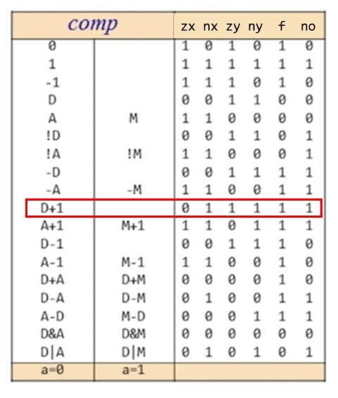
Below is a chart that shows in more detail all of the various computations this “Hack” ALU is capable of and what these control bits should be set to in order to accomplish that calculation. I’ve highlighted the increment calculation we walked through. D is the data register, but we can think of that as x in our case.
And for those following along in Python, we can test out that same exact logic using binary operators:
>>> x = 6
>>> # Increment the value using only binary operators
>>> ~((~x) + (-1))
7
It really makes you appreciate x++… (or x += 1 in Python).
Adding Sequential logic to Combinational Logic
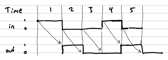
And then when I was finally getting used to the is-ness and isn't-ness of combinational logic, they threw sequential logic back into the mix. This thin layer of time and state draped around our combinational logic was difficult for me to understand at first. It’s also worth mentioning they give you a DFF (Data Flip-Flop) as another primitive gate much like the original Nand chip.
The output of a DFF chip at time t is whatever the input was at time t - 1. This is the fundamental building block of any chip that requires sequential processing such as registers, RAM chips, and the program counter.
The program counter was a relatively simple sequential chip that took me quite a while to figure out (ok, I may have looked up some “hints” on this one…).
Assembler
The final task of Part 1 was to write an assembler. The assembler allows you to write instructions in a more human-readable format, as opposed to writing 16-bit binary instructions by hand.
I wrote my assembler in Python. I’d consider this one of the more straight-forward assignments in the course. Most of the problem involved parsing assembly instructions and looking up values in the provided instruction tables.
The most interesting part of this was the “perspective” video where they talk about how this is our first layer of actual software within the Hack computer. That means we can extend our assembly language with additional abstractions.
Consider the following assembly code:
@100     # sets the address register to 100
 D=M      # sets the data register to the value stored at the address register
The instructors discuss how we could extend our assembler to accomplish the same functionality as above, but with a single instruction instead:
D=M[100] # combines the two instructions into one single line of assembly
We would have to write the additional logic into our assembly parser so that it understands how to interpret such an instruction. This new type of expression would ultimately resolve to the exact same machine code instructions as the prior two lines of assembly code.
The instructors also spent time discussing the design process of deciding what to implement in hardware and what to leave up to the software layer to figure out. Everything is a trade-off!
Conclusion / Thoughts
This has been an extremely challenging and fun course. I think it’s a great way to scratch that curiosity “itch” for learning how computers work without building a physical computer. (For those looking for something more physical and hands-on, Ben Eater has a Build-an-8-bit-computer-from-Scratch course along with a kit you can buy. That might be a future project for me as well).
That said, I do suspect that Part 2 of Nand 2 Tetris will be significantly more beneficial for someone in a Software Engineering or Developer role. I’m glad I completed Part 1, but I think the course instructors were wise to make Part 2 a stand-alone course itself.
Generally, you’ll gain the most practical understanding of your domain if you learn the abstraction level immediately below where you normally operate. For Software Engineers, this would likely be the Operating System and memory management.
As one parting note, I do think it’s important to acknowledge that we’re standing on the shoulders of giants while we write our high-level code in languages such as Python and JavaScript. Even if the complexity was not contained and things have gotten a bit out of control (that post is from Ryan Dahl, creator of Node JS and Deno).